Engine repair small engine module track lighting car detailing. Tach signal is a purple wire with a white trace pin r goes to ampseal optoin pin 30 ground the ampseal optoin pin 31 at the distributor advance control signal is a white wire pin e goes to ampseal pin 12.
 Click Rj45 Module Wiring Diagram 4 Channel Relay Cat6 For
With a gm hei 7 pin and 8 pin modules the ignition module wires you need to know about are.
gm ignition control module wiring diagram. Ignition control module icm circuit descriptions. It is recommended only for ordinary lawn garden equipment. Page 1 of 3.
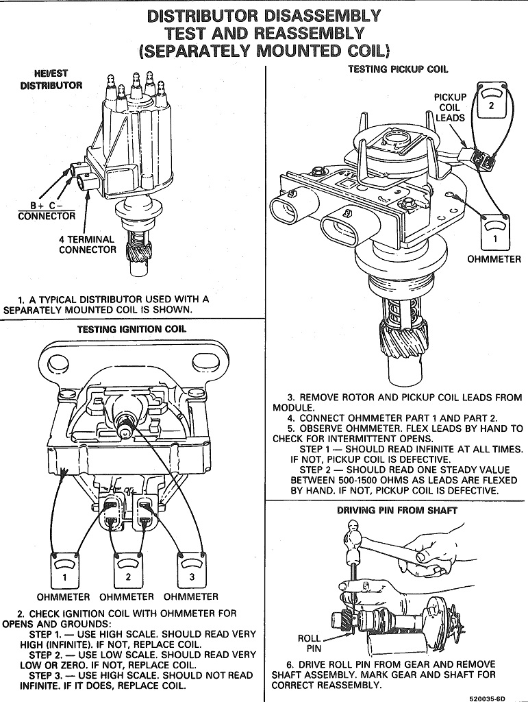
Gm 4 pin hei electronic ignition control module wiring connectionsdiagram with a magnetic pickup coil this electronic ignition system operates with full 12 volts. This tutorial will help you test the ignition coil ignition module and the crankshaft position sensor pickup coil. This module was new and unused it failed test 8 which is the est function.
Gm ignition control module wiring 2003 hyundai elantra fuse box 1992 bronco 5 0l wiring diagram 2003 ford 4 6l engine diagram bbq 055 smoker wiring diagram 6v generator wiring diagram b guitar wiring schematics 1992 dodge dakota ignition system wiring diagram 1965 mustang light wiring diagram saab 9000 radio wiring diagram automotive generator. Gm sells their vehicles under a wide range of name brands including pontiac chevrolet and buick. Gm hei distributor and coil wiring diagram.
How to test the gm distributor mounted ignition module. The ignition control module is used to switch primary current flow for the ignition coil and controls the ignition timing and strength. The ignition control module is responsible for turning.
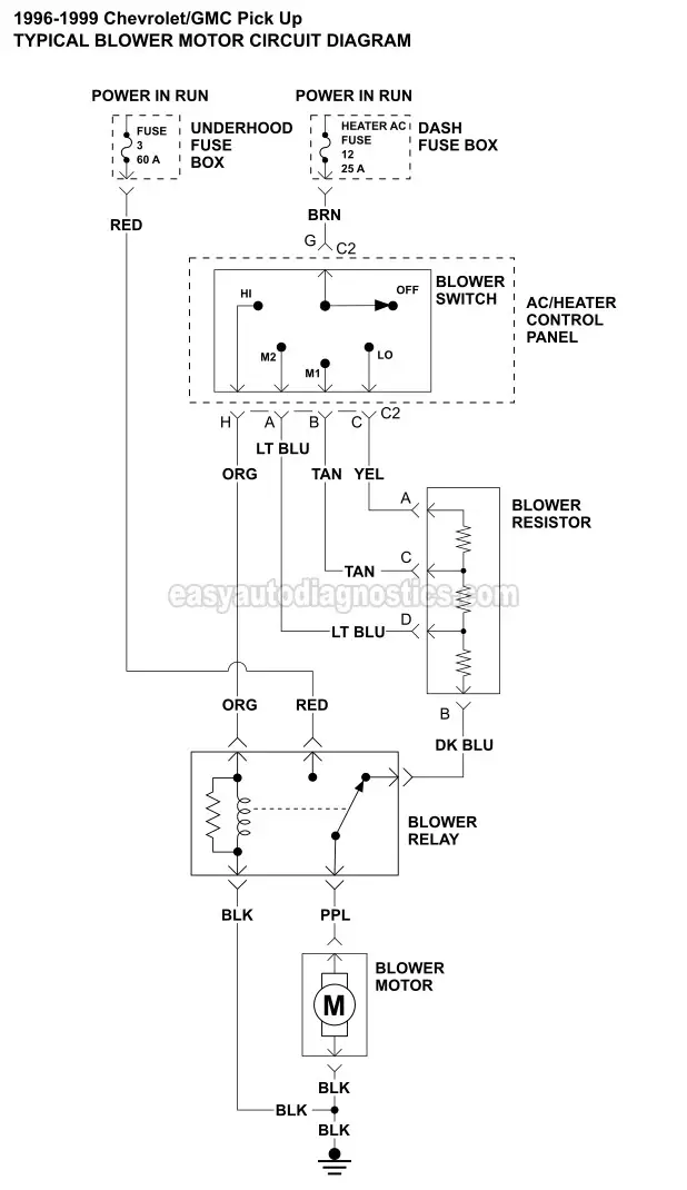
Ignition system circuit diagram 1996 1999 chevygmc pick up and suv. Gm vehicles are equipped with an ignition control module. Placement of the module varies from model to model so check the appropiate service manual of your vehicle for the exact location.
Ignition coil circuit descriptions. The 7 pin hei module. Diagram together with gm hei ignition module wiring diagram.
Symptoms of a bad ignition module and ignition coil. Locate the terminals running into and out of the ignition module. How to test the gm ignition control module 1995 2005.
The following diagram shows the honda vfr750r ignition system circuit and wiring diagram. Diagram together with gm hei ignition module wiring diagram. The typical ignition system circuit diagram for the 1996 1999 43l 50l and 57l 1500 2500 3500 pick up and suburban can be found here.
General motors inc designs and manufactures many different vehicles including trucks cars and minivans. Use a wiring diagram for the year model of your vehicle.
 23022 Ignition Control Module Wiring Diagram Digital Resources
 Gmc Sonoma 22 Engine Diagram Get Rid Of Wiring Diagram
 Part 1 Testing The Ignition Module And Crank Sensor Gm

 Apads Module Wiring Diagram Wiring Diagrams

 97 Tahoe Ignition Switch Wiring Diagram Wiring Diagrams
Comments
Post a Comment